Getting Started on a New Board
In part 1 of this series we found an interesting little board, and located the built-in UART pins. Let’s take a look at the output on boot:
console init done


U-Boot 2012.10 (Dec 07 2016 - 13:48:53) for GK7101 rb imx222 v1.00 (GOKE)

HAL:  20151223
DRAM:  128 MiB
Flash: 16 MiB
16 MiB
NAND:  SPINAND MID = 0xff, DID = 0xffff, Data = 0x1ffffff !spinand_board_init[1581]: No support this SPI nand!
SF: Detected GD25Q128C with page size 256 B, sector size 64 KiB, total size 16 MiB
In:    serial
Out:   serial
Err:   serial
Net:   arm_freq(600MHz)..............0x112032
use int MII..............
gk7101
Hit any key to stop autoboot:  5
Lots of useful information there. It’s an ancient version of Das U-Boot, the most commonly used bootloader for embedded Linux systems. Sure enough, it’s running Linux:
put param to memory
mem size (70)
bsb size (2)

the kernel image is zImage or Image
entry = 0xc1000000
## Transferring control to Linux (at address c1000000)...

Starting kernel ...

machid = 3988 r2 = 0xc0000100
Uncompressing Linux... done, booting the kernel.
[    0.000000] Booting Linux on physical CPU 0
[    0.000000] Linux version 3.4.43-gk (root@ubuntu) (gcc version 4.6.1 (crosstool-NG 1.18.0) ) #92 PREEMPT Wed Dec 7 16:55:36 CST 2016
[    0.000000] CPU: ARMv6-compatible processor [410fb767] revision 7 (ARMv7), cr=00c5387d
[    0.000000] CPU: VIPT aliasing data cache, VIPT aliasing instruction cache
[    0.000000] Machine: Goke GK7101 RB_IMX222 board V1.00
[    0.000000] Memory policy: ECC disabled, Data cache writeback
[    0.000000] AHB: 0x90000000  0xf2000000  -- 0x1000000
[    0.000000] APB: 0xa0000000  0xf3000000  -- 0x1000000
[    0.000000] PPM: 0xc0000000  0xc0000000  -- 0x200000
[    0.000000] BSB: 0xc4800000  0xf5000000  -- 0x200000
[    0.000000] DSP: 0xc4a00000  0xf6000000  -- 0x3600000
[    0.000000] hal version = 20151223
[    0.000000] Built 1 zonelists in Zone order, mobility grouping on.  Total pages: 17780
[    0.000000] Kernel command line: console=ttySGK0,115200 noinitrd mem=70M rw mtdparts=gk7101_flash:256K(boot),64K(bootenv),2560K(kernel),7168K(rootfs),1024K(rom),5312K(APP) rootfstype=squashfs root=/dev/mtdblock3 init=linuxrc ip=192.168.1.254:192.168.1.112:192.168.1.1:255.255.255.0:"gk7101":eth0 mac=3C:97:0E:22:E1:14 phytype=0
...
The system boots right into a BusyBox shell. Since the system has a microSD slot, the easiest way to take a good look at the firmware is to stick in a microSD card and just copy the built-in storage over to it. This way we can examine the goods with a much better set of tools than will be available on the camera.
The board has an SPI flash chip on it:
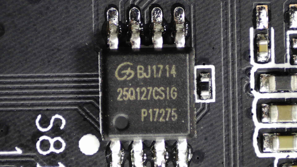
GigaDevice 16MB SPI flash
This isn’t like a hard disk or SSD, with a partition table of some sort to help the system figure out how the storage is structured. The Linux kernel needs to be told about the partitions. This version of U-Boot has this hardcoded, and it passes it along to the Linux kernel as part of the command line:
mtdparts=gk7101_flash:256K(boot),64K(bootenv),2560K(kernel),7168K(rootfs),1024K(rom),5312K(APP)
These partitions show up as /dev/mtdblock0, /dev/mtdblock1 and so on.
Das U-Boot is on the first partition, its configuration in the second,
Linux kernel on the next one followed by the root filesystem. The last
partition (“APP”) contains the main application the camera runs, and the “ROM”
partition contains configuration.
The mainline kernel has support for the basic ARM platform the GK7101 SoC uses,
ARM1176: Selecting CONFIG_ARCH_MULTI_V6 gets us working code, but of course
no I/O of any kind. The first thing the kernel outputs when U-Boot calls it
is normally the decompressor. It prints “Uncompressing Linux... done, booting the kernel.” to the console, then jumps into the kernel proper, at its new
location. The console, of course, is not so easy here: there is no BIOS that
will output this on a VGA port, like in X86. Instead, Linux has a very
low-level facility to have the decompressor use a memory-mapped UART as an
output-only console.
Normally, driving a UART would entail having an interrupt fire when e.g. a byte has arrived on the UART. At decompression time, however, the CPU has no interrupts, timers, or even MMU: U-Boot disables all that before handover. Therefore the decompressor’s UART driver can’t just write characters to a buffer, knowing that some timer will fire and empty the buffer into the UART registers as it clears itself. Instead, the driver has to check if the UART’s output register is clear, and only then write a single character.
This facility can also be used by the kernel once it’s up and running, but by
that time it will have a working MMU – and the I/O registers for the UART
may have moved to a different address. The kernel solves all of this by
allowing you to define 4 macros for your platform, and it uses these to
construct a putc() function.
From arch/arm/boot/compressed/debug.S:
ENTRY(putc)
    addruart r1, r2, r3
    waituart r3, r1
    senduart r0, r1
    busyuart r3, r1
    mov  pc, lr
ENDPROC(putc)
The addruart macro should load the base address for the UART registers –
the physical address in r1, and the corresponding virtual address in r2 (r3 is
just a scratch register it can use).
waituart should implement a busy loop waiting for the UART’s line status
register to show the output register is empty. senduart puts its first
argument into the output register, and busyuart again should implement a
busy loop waiting for output to clear – a flush() function.
Note how addruart loads the physical address into r1, and the other macros
then use r1. This is specific to the decompressor, since it runs pre-MMU. The
kernel facility that uses these macros instead calls them with addruart's
second argument.
So what’s the UART’s physical base address, and what do the registers look like? Only one way to find out: disassemble the vendor’s decompressor, and see what addresses it uses.
There are many disassemblers available, starting of course with GNU objdump. This is as good an occasion as any to try out a new tool that came out: Ghidra. It’s a reverse engineering suite in the style of the venerable IDA Pro. Unlike IDA, it’s open source – and very unlike anything, it was written and is maintained by the NSA. The code is right here on GitHub. It’s a little surreal to be using NSA code, but as it turns out the tool is very good. It supports a ton of architectures, and has a great decompiler – which, due to Ghidra’s internal architecture, automatically works on all supported CPUs.
The camera vendor’s version of Linux is a hacked-up 3.4.43. So compiling that
version from source and comparing the decompiled output with the source code
should go a long way to understanding the vendor’s code as well. The first
thing that gets sent to console is “Uncompressing Linux...”. This is done in
arch/arm/boot/compressed/misc.c, in function decompress_kernel(). The
call is to putstr(), a wrapper around the putc() function we saw defined
earlier. Following that should get us the macros we’re after.
Unfortunately the compiler inlined the putc function, so the loop has all the low-level I/O smeared into it Here’s the source code:
static void putstr(const char *ptr)
{
    char c;

    while ((c = *ptr++) != '\0') {
        if (c == '\n')
            putc('\r');
        putc(c);
    }

    flush();
}
This is Ghidra’s decompiled version of the vendor code:
void putstr(char *ptr)
{
    byte bVar1;
    uint uVar2;
    int *piVar3;

    piVar3 = *(int **)(PTR_DAT_c10008c0 + DAT_c10008c4 + -0x3efff7e4);
    while( true ) {
        bVar1 = *ptr;
        if (bVar1 == 0) break;
        if (bVar1 == 10) {
            do {
                uVar2 = (**(code **)(*piVar3 + 0x10))(DAT_c10008c8);
            } while ((uVar2 & 0x40) == 0);
            (**(code **)(*piVar3 + 0x1c))(0xd,DAT_c10008cc);
        }
        do {
            uVar2 = (**(code **)(*piVar3 + 0x10))(DAT_c10008c8);
        } while ((uVar2 & 0x40) == 0);
        (**(code **)(*piVar3 + 0x1c))((uint)bVar1,DAT_c10008cc);
        ptr = (char *)((byte *)ptr + 1);
    }
    while (uVar2 = (**(code **)(*piVar3 + 0x10))(DAT_c10008c8), (uVar2 & 4) != 0) {
        (**(code **)(*piVar3 + 0x10))(DAT_c10008cc);
    }
    return;
}
The DAT_ variables are references to memory addresses containing values,
which the instructions dereference. The ARM architecture has fixed 32-bit
instructions, so cannot handle direct register loads of 32-bit addresses. So
we’d expect to find these UART base addresses in variables like this.
That last while loop is the flush() function i.e. busyuart. Cleaned up and
with the variables filled in, it looks like this:
while (uVar2 = (somestruct + 0x10)(0xa0005014), (uVar2 & 4) != 0) {
    (somestruct + 0x10)(0xa0005004);
}
That looks like it reads from 0xa0005014 and waits for bit 2 to go low,
reading from 0xa0005004 while it’s not. In other words, that bit indicates
there’s stuff in the input buffer (it has one!), and drains it. So 0xa0005004
is the input buffer register.
But why is this using a function? The struct is somewhere in memory, and evidently the member at offset 0x10 is a pointer to a read function.
There’s only one line that sends putstr()'s string argument anywhere, so
that’s got to be the senduart macro’s implementation:
(**(code **)(*piVar3 + 0x1c))((uint)bVar1,DAT_c10008cc);
Cleaned up:
(somestruct + 0x1c)(bVar1, 0xa0005004);
So the mystery struct has a pointer to a write function at 0x1c, and the UART
output register is evidently 0xa0005004 as well.
Right before that is a busy loop, clearly the waituart macro:
    do {
        uVar2 = (**(code **)(*piVar3 + 0x10))(DAT_c10008c8);
    } while ((uVar2 & 0x40) == 0);
This reads 0xa0005014 in a loop, waiting for bit 6 to go high.
There is no implementation of addruart, as all address are hardcoded in
memory variables. But we have the addresses, and some bitfields. That should
be enough to make a kernel that boots and tells us it’s decompressing itself.
Progress!